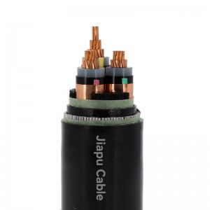
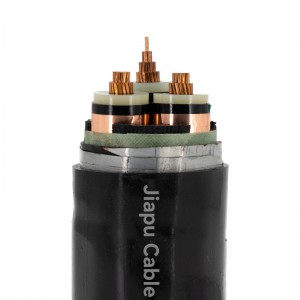
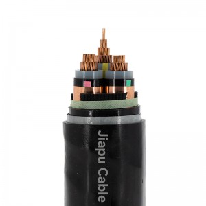
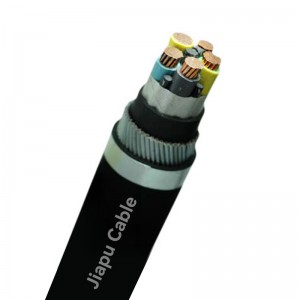
Electricity distribution or sub-transmission networks cable typically used as primary supply to Commercial, Industrial and urban residential networks. Suitable for high fault level systems rated up to 10kA/1sec. Higher fault current rated constructions are available on request.

Temperature range:
Minimum installation temperature: 0°C
Maximum operating temperature: +90°C
Minimum operating temperature: -25 °C
Minimum bending radius
Installed cables: 12D (PVC only) 15D (HDPE)
During installation: 18D (PVC only) 25D (HDPE)
Resistance to Chemical exposure: Accidental
Mechanical impact: Light (PVC only) Heavy (HDPE)
Water exposure: XLPE – Spray EPR – Immersion/Temporary coverage
Solar radiation and weather exposure: Suitable for direct exposure.
Construction:
Manufactured and Type Tested AS/NZS 1429.1, IEC: 60502-2 and other applicable standards
Formation – 1 core, 3 core, 3×1 core Triplex
Conductor – Cu or AL, Stranded Circular, Stranded Compact Circular, Milliken Segmented
Insulation – XLPE or TR-XLPE or EPR
Metallic screen or sheath – Copper Wire Screen (CWS), Copper Tape Screen (CTS), Lead alloy sheath (LAS), Corrugated Aluminium sheath (CAS), Corrugated Copper sheath (CCU), Corrugated Stainless Steel (CSS), Aluminium poly laminated (APL), Copper Poly Laminated (CPL), Aldrey wire screen (AWS)
Armour – Aluminium Wire Armoured (AWA), Steel Wire Armoured (SWA), Stainless Steel Wire Armoured (SSWA)
Polyethylene (HDPE) outer – alternative
Low smoke zero halogen (LSOH) – alternative
HV Cable Insulation XLPE has the following advantages:
1.Heat Resistance Performance:
XLPE with reticulated three-dimensional structure has very excellent heat resistance performance. It will not decompose and carbonize below 300℃, the long-term working temperature can reach 90℃, and the thermal life can reach 40 years.
2.Insulation Performance:
XLPE maintains the original good insulation characteristics of PE, and the insulation resistance is further increased.
Its dielectric loss angle tangent value is very small, and it is not greatly affected by temperature.
3.Mechanical Properties:
Due to the establishment of new chemical bonds between macromolecules, the hardness, stiffness, abrasion resistance, and impact resistance of XLPE have been improved, thus making up for the shortcomings of PE which is susceptible to environmental stress and cracking.
4.Chemical Resistance Characteristics:
XLPE has strong acid and alkali resistance and oil resistance, and its combustion products are mainly water and carbon dioxide, which are less harmful to the environment and meet the requirements of modern fire safety.
6.35/11kV-Power cable
| Cores x Nominal Area | Conductor diameter (Approx.) | Nominal Insulation Thickness | Approx. CWS area on each core | Nominal Thickness of PVC Sheath | Overall Cable diameter (+/- 3.0) | Short Circuit rating of Conductor/ CWS | Cable Weight (Approx.) | Max. Conductor DC Resistance at 20 °C |
| No. x mm2 | mm | mm | mm2 | mm | mm | kA for 1sec | kg/km | (Ω/km) |
| 1C x 35 | 7.0 | 3.4 | 24 | 1.8 | 23.6 | 5 / 3 | 1044 | 0.524 |
| 1C x 50 | 8.1 | 3.4 | 24 | 1.8 | 24.7 | 7.2 / 3 | 1205 | 0.387 |
| 1C x 70 | 9.7 | 3.4 | 79 | 1.8 | 28.4 | 10 / 10 | 1955 | 0.268 |
| 1C x 95 | 11.4 | 3.4 | 79 | 1.8 | 30.1 | 13.6 / 10 | 2219 | 0.193 |
| 1C x 120 | 12.8 | 3.4 | 79 | 1.9 | 31.4 | 17.2 / 10 | 2480 | 0.153 |
| 1C x 150 | 14.2 | 3.4 | 79 | 1.9 | 32.8 | 21.5 / 10 | 2794 | 0.124 |
| 1C x 185 | 16.1 | 3.4 | 79 | 2.0 | 34.3 | 26.5 / 10 | 3146 | 0.0991 |
| 1C x 240 | 18.5 | 3.4 | 79 | 2.0 | 36.5 | 34.3 / 10 | 3698 | 0.0754 |
| 1C x 300 | 20.6 | 3.4 | 79 | 2.1 | 38.6 | 42.9 / 10 | 4307 | 0.0601 |
| 1C x 400 | 23.6 | 3.4 | 79 | 2.2 | 42.0 | 57.2 / 10 | 5295 | 0.0470 |
| 1C x 500 | 26.6 | 3.4 | 79 | 2.3 | 45.2 | 71.5 / 10 | 6280 | 0.0366 |
| 1C x 630 | 30.2 | 3.4 | 79 | 2.4 | 49.0 | 90.1 / 10 | 7550 | 0.0283 |
More Product


 Send An Email

